Instrument hook-up refers to the process of connecting various instruments or devices to a control system or process piping system in order to facilitate data acquisition, monitoring, and control of a particular process. This typically involves connecting various types of sensors, transmitters, controllers, and other devices to the process piping system or control system, as well as providing power and signal wiring to those devices.
Instrument hook-up is an important step in the overall process of process control and automation, and it is typically carried out by trained professionals with expertise in instrumentation and control systems. Proper instrument hook-up is essential to ensure accurate and reliable data acquisition and control, as well as to ensure the safety and efficiency of the overall process.
Advantages of Instrument Hook-up Diagram
Instrument Hook-up drawings have several advantages in the field of process control and automation. Some of the key advantages are:
Provides a detailed understanding of the system: Instrument Hook-up drawings provide a detailed representation of the entire system, including the location of all instruments, the type of instruments used, and their connection to the control system or process piping system. This helps in understanding the system in detail and identifying any issues or problems that may arise during operation.
Helps in installation and maintenance: Instrument Hook-up drawings provide a clear and concise understanding of the installation process, making it easier for technicians to install and maintain the instruments. It also helps in troubleshooting any issues that may arise during the installation or maintenance process.
Facilitates communication: Instrument Hook-up drawings help in facilitating communication between different stakeholders involved in the process, including operators, engineers, technicians, and maintenance personnel. It helps in ensuring that everyone has a clear understanding of the system and their roles and responsibilities.
Improves safety: Proper Instrument Hook-up drawings ensure that the instruments are installed and connected correctly, reducing the risk of accidents or equipment failure. It also helps in identifying any potential safety hazards and taking appropriate measures to mitigate them.
Enhances efficiency: Instrument Hook-up drawings provide a standardized approach to the installation and maintenance of instruments, reducing the time and effort required for these processes. It also helps in improving the overall efficiency of the process control and automation system
Types of Instrument Hook-up Drawings:
There are several types of Instrument Hook-up diagrams used in the field of process control and automation. The most common types are:
Pneumatic Hook-up Diagram: This type of diagram is used to show the pneumatic connections between various instruments and the control system. It includes details of the air supply, pressure regulators, filters, and other components that are used in the system.
Hydraulic Hook-up Diagram: Hydraulic Hook-up Diagrams are used to show the hydraulic connections between various instruments and the control system. It includes details of hydraulic pumps, pressure regulators, filters, and other components that are used in the system.
Electrical Hook-up Diagram: This type of diagram shows the electrical connections between various instruments and the control system. It includes details of wiring, junction boxes, terminations, and other components that are used in the system.
Process Hook-up Diagram: Process Hook-up Diagrams show the connections between various instruments and the process piping system. It includes details of process flow, valves, piping, and other components that are used in the system.
Structural Hook-up Diagram: Structural Hook-up Diagrams show the location of instruments and the control system in relation to the overall structure of the process plant. It includes details of supports, brackets, and other components that are used to mount the instruments and the control system.
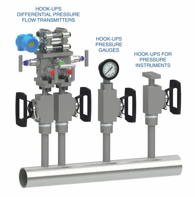
Each of these Instrument Hook-up diagrams provides specific information about the connections and components used in the process control and automation system, and they are used by engineers, technicians, and operators to understand and maintain the system. A typical image for instrument hook-ups is provided in Fig. 1 (Image Credit: fluidcontrols.com) below
Inclusions of instrument Hook-up Drawing
An Instrument Hook-up Drawing is a detailed engineering drawing that shows the interconnection between various instruments, devices, and equipment in a process control system. The following are the typical items that are included in an Instrument Hook-up Drawing:
Instrument Identification: The Instrument Hook-up Drawing includes a list of all the instruments that are used in the process control system, and each instrument is identified by a tag number.
Process Piping: The Instrument Hook-up Drawing shows the process piping that connects the instruments to the process, along with details of valves, fittings, and other components.
Electrical Wiring: The Instrument Hook-up Drawing shows the electrical wiring that connects the instruments to the control system, including details of junction boxes, cable trays, and other components.
Pneumatic or Hydraulic Connections: The Instrument Hook-up Drawing shows the pneumatic or hydraulic connections that are used to control the instruments, including details of regulators, filters, and other components.
Instrument Mounting: The Instrument Hook-up Drawing shows the location of each instrument, along with details of the mounting hardware, supports, and brackets used to secure the instruments.
Control System: The Instrument Hook-up Drawing shows how the instruments are connected to the control system, including details of the control panel, junction boxes, and other components.
Legends and Symbols: The Instrument Hook-up Drawing includes a legend that explains the symbols and abbreviations used on the drawing.
Overall, the Instrument Hook-up Drawing provides a comprehensive view of the process control system, and it is an essential tool for engineers, technicians, and operators to understand and maintain the system.
Applications of Instrument Hook-up Diagrams:
Instrument Hook-up Diagrams are used in a wide range of applications in the field of process control and automation. Some of the common applications of Instrument Hook-up Diagrams are:
Process Control: Instrument Hook-up Diagrams are used to control the various processes involved in manufacturing, refining, and other industrial processes. The diagrams help in identifying the location of instruments and how they are connected to the control system, which is essential for ensuring the efficient and safe operation of the process.
Automation: Instrument Hook-up Diagrams are used in the automation of various processes, including manufacturing, transportation, and distribution. The diagrams provide a detailed understanding of the instruments used in the system and how they are connected to the control system, which is essential for automating the process.
Maintenance and Troubleshooting: Instrument Hook-up Diagrams are used for maintenance and troubleshooting of the process control system. The diagrams provide a detailed understanding of the connections between instruments, piping, wiring, and other components, which is essential for identifying and resolving any issues that may arise.
Safety: Instrument Hook-up Diagrams are used for ensuring the safety of personnel and equipment in industrial processes. The diagrams provide a detailed understanding of the location of instruments and how they are connected to the control system, which is essential for identifying any potential safety hazards and taking appropriate measures to mitigate them.
Overall, Instrument Hook-up Diagrams are essential for ensuring the efficient and safe operation of process control systems, and they are used in a wide range of applications in various industries.
Examples of Instrument Hook-ups
Instrument Hook-up Diagrams are typically prepared for a wide range of instruments used in a process control system. Some of the common instruments for which Hook-up Diagrams are prepared are:
Flow meters: Flow meters are used to measure the flow of liquids, gases, and other materials in a process control system. Hook-up diagrams for flow meters show the location of the meter and the piping and valves used to control the flow.
Pressure transmitters: Pressure transmitters are used to measure the pressure of liquids and gases in a process control system. Hook-up diagrams for pressure transmitters show the location of the transmitter and the piping and valves used to control the pressure.
Temperature sensors: Temperature sensors are used to measure the temperature of liquids, gases, and other materials in a process control system. Hook-up diagrams for temperature sensors show the location of the sensor and the wiring and other components used to control the temperature.
Level transmitters: Level transmitters are used to measure the level of liquids and other materials in a process control system. Hook-up diagrams for level transmitters show the location of the transmitter and the piping and valves used to control the level.
Control valves: Control valves are used to control the flow, pressure, and temperature of liquids, gases, and other materials in a process control system. Hook-up diagrams for control valves show the location of the valve and the piping and other components used to control the process.
Analytical instruments: Analytical instruments such as pH sensors, conductivity sensors, and gas analyzers are used to measure the chemical composition of materials in a process control system. Hook-up diagrams for analytical instruments show the location of the instrument and the wiring and other components used to control the process.
Actuators: Hook-up Diagrams are prepared for actuators, which are used to control the movement of valves, dampers, and other process control equipment.
Overall, Instrument Hook-up Diagrams can be prepared for any instrument used in a process control system, and they provide a detailed understanding of the connections and components used in the system.
Steps for Preparing Instrument Hook-up Drawing
Preparing an Instrument Hook-up Drawing requires a systematic approach, and the following are the typical steps involved in the process:
Identify the instruments: The first step is to identify all the instruments that are required for the process control system. This includes flow meters, pressure instruments, temperature instruments, level instruments, analytical instruments, control valves, and actuators.
Determine the instrument location: The next step is to determine the location of each instrument in the process piping system. This includes identifying the location of process taps, nozzles, and other connection points.
Determine the piping connections: The third step is to determine the piping connections between the instruments and the process. This includes identifying the type of piping (e.g., carbon steel, stainless steel, PVC) and the size of piping (e.g., 1 inch, 2 inches, etc.).
Determine the electrical connections: The fourth step is to determine the electrical connections between the instruments and the control system. This includes identifying the type of wiring (e.g., copper, aluminum) and the size of the wiring (e.g., 14 AWG, 12 AWG, etc.).
Determine the pneumatic or hydraulic connections: The fifth step is to determine the pneumatic or hydraulic connections between the instruments and the control system. This includes identifying the type of regulator, filter, and other components required for the system.
Determine the instrument mounting details: The sixth step is to determine the instrument mounting details, including the type of support and brackets required for the instrument.
Create the Hook-up Drawing: The final step is to create the Instrument Hook-up Drawing, which includes all the details of the instrument connections, piping, electrical wiring, pneumatic or hydraulic connections, and instrument mounting details.
Overall, preparing an Instrument Hook-up Drawing requires careful planning and coordination between the process engineer, piping engineer, electrical engineer, and instrumentation engineer, and it is essential for ensuring the efficient and safe operation of the process control system.
They might allow yoou to steamjroll other metrics to the
fore, but they alone aren’t doing a lot for you.
Hello Anup
Your description about Hook up drawings is very informative.
Would you be able to design hook up drawings for Analytical Instruments like pH, ORP, Conductivity, Iron, Silica Analysers etc..