Gear pumps are a type of positive displacement pump widely used in various industries to transfer fluids, primarily liquids, from one place to another. They are known for their simple yet effective design and ability to handle a wide range of viscosities. In this comprehensive guide, we will delve into every aspect of gear pumps, from their working principles and types to their applications, advantages, disadvantages, and maintenance.
1. Introduction to Gear Pumps
What Are Gear Pumps?
A gear pump is a type of positive displacement pump that uses rotating gears to transfer fluids. It operates on the principle of trapping and displacing a fixed amount of fluid with each rotation of the gears. As the gears rotate, they create a low-pressure area at the inlet, allowing fluid to enter the pump. The fluid is then transported through the pump’s internal cavities before being expelled at the outlet.
Historical Overview
The concept of gear pumps dates back to ancient civilizations, where rudimentary forms of gear mechanisms were used for various purposes. However, it was during the industrial revolution in the 19th century that gear pumps began to take a more recognizable form. In 1905, a patent for an external gear pump was granted to Johannes Gillain and Felix Wankel, two German engineers. This design laid the foundation for modern gear pump technology.
Basic Components
Gear pumps consist of several essential components:
- Housing: The housing is the outer casing of the pump, which encloses all the other components. It provides structural support and helps maintain the alignment of the gears.
- Gears: Gear pumps have two or more intermeshing gears that rotate inside the housing. These gears are typically made of materials like steel or bronze.
- Inlet and Outlet Ports: These are the openings in the housing that allow fluid to enter and exit the pump. The inlet port is connected to the fluid source, while the outlet port is connected to the destination.
- Drive Shaft: The drive shaft is connected to an external power source, such as an electric motor or an internal combustion engine. It transmits rotational motion to the gears.
- Bearings: Bearings support the rotating components, reducing friction and wear.
- Seals and Gaskets: Seals and gaskets are used to prevent fluid leakage at various points in the pump, ensuring a tight seal between moving and stationary parts.
2. Working Principles
Positive Displacement
Gear pumps operate on the positive displacement principle, which means they move a fixed volume of fluid with each rotation of the gears. This makes them ideal for applications where precise flow control is required. Unlike centrifugal pumps, which rely on kinetic energy to move fluids, gear pumps provide a consistent and predictable flow rate regardless of the pressure.
Gear Types
Gear pumps come in two primary types based on the arrangement of their gears:
External Gear Pumps
- External gear pumps consist of two gears—one is the driving gear (connected to the drive shaft), and the other is the driven gear. These gears mesh externally, with the driving gear turning the driven gear.
- The fluid is trapped between the gear teeth and the housing as the gears rotate. As the gears continue to mesh, the fluid is forced to move from the inlet to the outlet, resulting in a continuous flow.
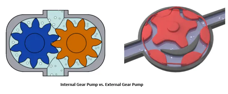
Internal Gear Pumps
- Internal gear pumps, also known as “Gerotor” pumps, have a more complex design. They consist of an inner rotor with fewer teeth and an outer rotor with more teeth. These rotors are designed to mesh internally, with the inner rotor being driven by the drive shaft.
- As the inner rotor rotates, it drives the outer rotor. The fluid is trapped in the spaces between the rotor lobes and the pump housing, causing it to move from the inlet to the outlet.
Gear Pump Operation
The operation of a gear pump can be broken down into several steps:
- Inlet Phase: When the gears begin to rotate, fluid is drawn into the pump through the inlet port. As the gears continue to turn, the space between the gear teeth and the pump housing increases, creating a low-pressure area that allows fluid to flow in.
- Transport Phase: As the gears rotate further, the fluid becomes trapped in the spaces between the gear teeth and the housing. The rotating gears carry the trapped fluid from the inlet side to the outlet side.
- Outlet Phase: Once the fluid reaches the outlet side, it is pushed out of the pump through the outlet port. The meshing of the gears and the reduction in volume between the gear teeth and the housing force the fluid out of the pump.
- Repeating Cycle: This process repeats with each rotation of the gears, resulting in a continuous flow of fluid. The volume of fluid moved per rotation is determined by the size and geometry of the gears.
3. Types of Gear Pumps
Gear pumps come in several variations, each with its own advantages and ideal applications. The three primary types are external gear pumps, internal gear pumps (Gerotor pumps), and helical gear pumps.
External Gear Pumps
External gear pumps are one of the most common types of gear pumps. They consist of two gears—one driving gear and one driven gear—both of which are external to the pump housing. The driving gear is typically connected to a motor or an engine and rotates, driving the driven gear. Fluid is transferred between the gear teeth and the pump housing. Here are some key characteristics of external gear pumps:
- Simple Design: External gear pumps are known for their straightforward design, making them easy to manufacture and maintain.
- High Efficiency: They can achieve relatively high levels of efficiency, making them suitable for various applications.
- Precise Flow Control: External gear pumps offer precise flow control and can handle a wide range of viscosities.
- Common Applications: These pumps are used in hydraulic systems, lubrication systems, and various industrial processes.
Internal Gear Pumps (Gerotor Pumps)
Internal gear pumps, also known as Gerotor pumps, have a more complex internal structure. They consist of an inner rotor with fewer teeth and an outer rotor with more teeth. The inner rotor is connected to the drive shaft and drives the outer rotor. Fluid is transferred in the spaces between the rotor lobes and the pump housing. Key features of internal gear pumps include:
- Compact Design: Gerotor pumps have a compact design, making them suitable for applications with limited space.
- Smooth Flow: They provide a smooth and continuous flow of fluid, making them ideal for applications requiring constant pressure.
- Low Noise: Gerotor pumps are quieter in operation compared to some other types of gear pumps.
- Common Applications: They are commonly used in automotive applications, such as engine oil pumps, as well as in hydraulic systems and some industrial processes.
Helical Gear Pumps
Helical gear pumps, also known as herringbone gear pumps or double helical gear pumps, have a unique gear arrangement that reduces pulsation in the flow. They consist of two intermeshing gears with helical teeth. The helical shape of the teeth helps in reducing noise and vibration in the pump operation. Some key characteristics of helical gear pumps include:
- Reduced Pulsation: The helical gear design results in a smoother and more uniform flow, reducing pressure pulsations.
- Low Noise and Vibration: The helical gears create less noise and vibration compared to some other gear pump types.
- Applications: Helical gear pumps are used in applications where a continuous, uniform flow is critical, such as in the chemical and food processing industries.
4. Advantages of Gear Pumps
Gear pumps offer several advantages that make them suitable for a wide range of applications:
Precise Flow Control
One of the most significant advantages of gear pumps is their ability to provide precise flow control. Since they operate on the positive displacement principle, the flow rate is directly proportional to the speed of the pump and can be easily controlled by adjusting the pump’s rotational speed. This makes gear pumps suitable for applications where accurate dosing or metering of fluids is required.
Self-Priming
Gear pumps are often self-priming, meaning they can draw fluid into the pump without the need for external priming. This makes them ideal for situations where the pump needs to start and operate reliably even when the fluid source is below the pump’s inlet.
Handles High Viscosity Fluids
Gear pumps are well-suited for handling high-viscosity fluids, such as thick oils and syrups. Their positive displacement nature ensures that they can move these viscous liquids effectively, making them valuable in applications where other pump types may struggle.
Compact and Simple Design
The simple design of gear pumps makes them easy to manufacture and maintain. They have relatively few moving parts, reducing the risk of mechanical failure. This simplicity also contributes to their compact size, making them suitable for applications with limited space.
Wide Range of Applications
Gear pumps find use in a wide range of industries and applications, including hydraulic systems, lubrication systems, food and beverage processing, chemical processing, and automotive systems. Their versatility stems from their ability to handle different viscosities and provide precise flow control.
5. Disadvantages of Gear Pumps
While gear pumps offer many advantages, they also have some limitations and disadvantages that should be considered:
Limited Pressure Handling
One of the main limitations of gear pumps is their relatively limited ability to handle high pressures compared to other pump types like piston pumps or centrifugal pumps. They are better suited for low to moderate-pressure applications.
Sensitivity to Fluid Viscosity
While gear pumps can handle high-viscosity fluids, they are sensitive to changes in fluid viscosity. Variations in viscosity can affect the pump’s performance and efficiency, making it necessary to choose the right type of gear pump for the specific fluid being pumped.
Noisy Operation
Gear pumps can be noisy during operation, especially at higher speeds. The meshing of gear teeth can produce a characteristic whining or churning sound. This noise can be a concern in applications where noise levels need to be minimized.
Limited Efficiency
Gear pumps may not be as energy-efficient as some other pump types. Their efficiency can vary depending on factors like speed, fluid viscosity, and pressure. In applications where energy efficiency is a primary concern, other pump types might be more suitable.
6. Applications
Gear pumps have a wide range of applications across various industries due to their ability to handle different fluids and provide precise flow control. Here are some common applications:
Industrial Uses
Gear pumps are employed in industrial settings for processes such as transferring chemicals, adhesives, and paints. They are also used in hydraulic power units to generate hydraulic pressure for machinery and equipment.
Automotive Industry
Gear pumps are commonly found in vehicles, where they are used for engine oil circulation, fuel injection, and power steering systems. Their compact design and ability to provide consistent flow make them ideal for automotive applications.
Hydraulic Systems
Hydraulic systems in construction machinery, agricultural equipment, and manufacturing machinery often rely on gear pumps to provide the hydraulic power needed for tasks like lifting heavy loads and controlling equipment.
Lubrication Systems
Gear pumps play a crucial role in lubrication systems by circulating oil or grease to lubricate moving parts in machinery and engines. They ensure that vital components are adequately lubricated to reduce friction and wear.
Food and Beverage Industry
In the food and beverage industry, gear pumps are used to transfer various products, including syrups, chocolate, and sauces. Their ability to handle high-viscosity fluids makes them valuable in food processing and packaging applications.
7. Maintenance and Troubleshooting
To ensure the reliable operation of gear pumps and prolong their service life, proper maintenance and troubleshooting procedures are essential.
Maintenance Tips
- Regular Inspection: Periodically inspect the pump for signs of wear, leaks, or damage to seals and gaskets.
- Lubrication: Ensure that the gears and bearings are adequately lubricated to reduce friction and wear.
- Cleanliness: Maintain a clean environment around the pump to prevent contaminants from entering and potentially damaging the gears or other components.
- Viscosity Control: Choose the appropriate gear pump type and size for the specific fluid and viscosity being handled.
- Temperature Control: Monitor and control the operating temperature of the pump to prevent overheating and potential damage to seals and gaskets.
Common Issues
- Leakage: Fluid leakage is a common issue and can be caused by damaged seals or gaskets. Regularly check for leaks and replace any damaged components.
- Cavitation: Cavitation occurs when the pump operates at a low inlet pressure, causing the formation of vapor bubbles in the fluid. These bubbles can collapse, leading to damage to the gears and other components. Ensure that the pump is adequately primed and that the inlet pressure is within the recommended range.
- Excessive Noise and Vibration: Noisy operation can be caused by misalignment of gears or worn bearings. Address any alignment issues and replace worn components as needed.
- Overheating: Overheating can occur if the pump operates at high speeds or under excessive pressure. Ensure that the pump is operating within its specified limits and that cooling mechanisms are in place if necessary.
Troubleshooting Procedures
- Check for Blockages: If the pump is not drawing fluid or has reduced flow, check for blockages in the inlet or outlet ports and clear them if necessary.
- Inspect Seals and Gaskets: Examine the seals and gaskets for signs of damage or wear. Replace any components that show signs of deterioration.
- Monitor Fluid Viscosity: If the pump is struggling to handle high-viscosity fluids, consider heating the fluid or using a different pump type better suited to the viscosity.
- Check for Mechanical Issues: Investigate any unusual noise or vibration during operation. Misalignment of gears or worn bearings can be common sources of these problems.
- Review Operating Parameters: Ensure that the pump is operating within the specified speed, pressure, and temperature limits. Adjust parameters as needed to optimize performance.
8. Conclusion
Gear pumps are versatile and widely used in various industries due to their precise flow control, ability to handle high-viscosity fluids, and compact design. While they have some limitations, such as pressure handling capabilities and sensitivity to fluid viscosity, these pumps continue to play a vital role in processes ranging from automotive systems and hydraulic machinery to food processing and industrial applications.
Understanding the principles of gear pump operation, the different types available, their advantages, disadvantages, and maintenance requirements is essential for engineers, technicians, and professionals working in fields where fluid transfer and flow control are critical. With proper care and consideration of their unique characteristics, gear pumps can provide reliable service for many applications, contributing to the efficient and effective operation of various systems and processes.
9. Frequently Asked Questions
Q1. What is the principle of operation for gear pumps?
A1. Gear pumps operate on the principle of positive displacement. They use meshing gears to trap and transfer fluid from the inlet to the outlet, delivering a fixed volume of fluid per revolution.
Q2. What are the main types of gear pumps?
A2. The main types of gear pumps are external gear pumps (including spur, helical, and herringbone gear pumps) and internal gear pumps (including rotary gear pumps and lobe pumps).
Q3. Where are gear pumps commonly used?
A3. Gear pumps find applications in various industries, including automotive, chemical processing, food and beverage, oil and gas, pharmaceuticals, and manufacturing, due to their versatility and precision.
Q4. What are the advantages of gear pumps?
A4. Gear pumps offer precise flow control, high-pressure capability, a wide viscosity range, compact design, and durability.
Q5. What are the disadvantages of gear pumps?
A5. Gear pumps have limited suction lift capabilities, may not be suitable for shear-sensitive or abrasive fluids, and can produce noise and vibration.
Q6. How can gear pumps be maintained?
A6. Maintenance of gear pumps involves regular inspections, lubrication, seal replacement, gear alignment checks, and cleaning to ensure proper performance and longevity.
Q7. What are common troubleshooting issues with gear pumps?
A7. Common troubleshooting issues with gear pumps include leakage, low flow rate, excessive noise/vibration, overheating, and cavitation. Addressing these issues promptly is essential to maintain pump performance.
Q8. What are the codes and standards for gear pumps?
A8. The design, manufacturing, and use of gear pumps are subject to various codes and standards as mentioned below:
- API 676
- ISO 5199, ISO 2858, and ISO 3661
- ANSI/HI 3.1-3.5
- ASME B73.1
- EN 809