A Safety Instrumented System or SIS is a distinct and reliable system consisting of an engineered set of hardware and software controls to avoid the catastrophic release of explosive, toxic, or flammable fluids. In critical process systems of refineries, chemical plants, nuclear facilities, etc. safety instrumented system plays a major role in safeguarding the process. Using safety instrumented system control elements sensors and logic solvers are added to bring any process to a safe condition when predetermined logic is violated. Safety instrumented systems are designed following IEC 61511, IEC 61508, and ISA S84.01 standard guidelines. In this article, we will explore the basics of safety instrumented systems.
Components of a Safety Instrumented System
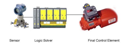
To protect against various process hazards in the plant, the Safety Instrumented System is designed to implement single or multiple functions. To properly function, Each SIS consists of three essential components:
- A sensor (temperature, pressure, density, flow sensor, etc.) to monitor the process. These sensors detect any abnormal process conditions during plant operation.
- A logic device (Safety PLC, Controller Systems, etc.)
- to receive the signal from the sensor
- to determine if the condition is hazardous,
- to send a signal to take action
- A final control device (On /Off Valves, Actuators, Safety Relays, etc.) to implement appropriate plant action upon receiving the signal from the logic device.
Note that, all the above three elements of the Safety Instrumented System should function as designed for safely isolating the process plant during an emergency.
Examples of Safety Instrumented Systems (SIS)
Basically, the Safety Instrumented Systems monitor some predefined values and parameters of an operating plant, and when abnormal conditions occur, they alarm and place the plant in a safe or even at the shutdown condition. Typical examples of a few safety instrumented systems are
- The SIS on a high fuel gas pressure line initiates action to close the main fuel gas valve during an over-pressure situation.
- A very high reactor temperature is detected by SIS and it initiates action to open the cooling media valve to make the system safe.
- Upon detection of high distillation column pressure by the SIS, it initiates action to open a pressure vent valve.
Emergency Shutdown (ESD) Systems, Emergency Venting (ESV) Systems, Safety Shutdown Systems, High-integrity Pressure Protection systems, Safety Interlock Systems, etc. are typical examples of safety instrumented systems.
The SIS consists of several safety instrumented functions (SIF). Each SIF has a specified safety integrity level (SIL), which is necessary to achieve functional safety.
Safety Instrumented System Design
The design of safety-instrumented systems must be independent of all other control systems for the same equipment or process. All of the control elements in an SIS shall be dedicated solely to the proper functioning of the SIS. While designing an SIS system the following guides must be kept in mind:
- An SIS is a Risk Reduction measure.
- Before starting the SIS design all reliability data of the equipment, instruments, and systems must be collected.
- The design must foresee the causes of common failure.
- SIS loop components must be standardized high-quality elements.
Safety Integrity Level (SIL)
Safety integrity levels are a quantifiable way to establish safety performance targets and a key safety metric for SIS systems. Four possible Safety Integrity Levels are defined by IEC standards. They are SIL 1, SIL 2, SIL 3, and SIL 4. However, ISA S84.01 defines only up to SIL 3. They are categorized as follows:
- “SIL 4”- Catastrophic impact on the community.
- “SIL 3”- Protection of employees and the community.
- “SIL 2”- Protection of production and property. Possible damages to employees.
- “SIL 1”- Little impact on the property and protection of production.
In terms of SIL levels, with an increase in SIL level, the cost increases due to more complex and stricter hardware and software specifications
Probability of Failure Upon Demand (PFD)
The PFD or probability of failure on demand indicates the probability that the SIS system will not perform its intended operation (fail to perform its safety function) when required. It is required to calculate the probability of failure on demand (PFD) by understanding how the components of the SIS system can fail. The PFD for any SIS system is obtained by adding PFDs for each element of the system:
PFDtotal=PFDsensor+ PFDlogic solver+ PFDfinal control element
For determining the PFD of each element, documented failure rate data for each element must be collected.
Online Courses on Safety Instrumented System
Various online courses are available to develop your knowledge further on safety Instrumented Systems. Some of them are listed below for your review and enrollment: